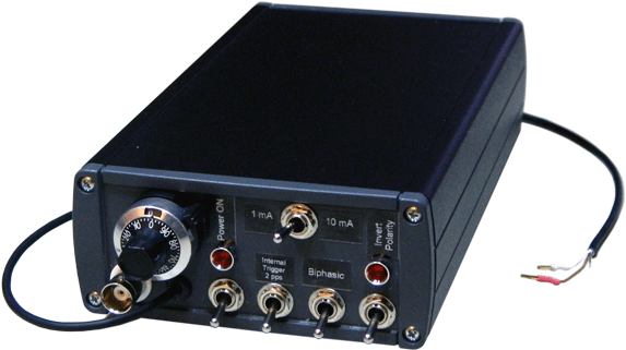

The electrostimulator is designed primarily for the brain stimulation of the laboratory animals in the electrophysiological experiments. Its design is optimized for minimization of electrical interferences (artifacts) during recording of neuronal activity by high-impedance electrodes. To minimize artifacts the device is batteries-powered. Electronics and the power source are encapsulated in a compact cage. The device has build-in pulse generator that eliminates a need in an external generator or another trigger source in most cases. If usage of external trigger source is desirable, for instance,for precise synchronization with other equipment, this is also possible. The electrostimulator has the trigger input optically isolated from the stimulating electronics.
The stimulator produces current pulses of 200 uS duration. They can be positive, negative, and biphasic (i.e. the first 200 uS positive pulse is followed by 200 uS negative pulse) and inversed (i.e. the negative pulse goes first). If the internal trigger is used, the pulses follow with the time interval 512 mS (i.e. approximately two pulses per second). If the external trigger is used, the pulse is generated at every rising edge. The external source should be capable to provide a 5 V pulse with 15 mA current. The relatively high triggering current is necessary because this input drives the opto-pair directly. The amplitude of output current pulses is adjustable in range 0-10 mA. The typical stimulating current is 100 uA.
The stimulator is shipped with the batteries and is ready just after unpacking. The capacity of batteries is sufficient for two years of usual exploitation. If the LEDs on the frontal panel don’t blink as they should or the output current of the stimulator is smaller than this is set on the scale replace the batteries how this is described in the last section.
The functions of controlling elements on the frontal panel (see picture below) are clear from their labels. The stimulating current is set by the knob “Current adjustment” and the switch “1 mA – 10 mA” (“Range selector”). The usual range is 1 mA. This means that the whole scale of the knob is 1 mA. The numbers in the small window of the knob change from 0 to 10. Thus, to set stimulating current 100 uA there should be “1”, i.e. 1/10 of the 1 mA scale. The values on the ring are for the fine adjustment. For setting 150 uA it should be “1” in the small window and “50” on the rotating scale.